Abstract
Robotic Wire Arc Additive Manufacturing (WAAM) is a metal additive manufacturing technology offering flexible 3D printing while ensuring high-quality near-net-shape final parts. However, WAAM also suffers from geometric imprecision, especially for low-melting-point metal such as aluminum alloys. In this paper, we present a multi-robot framework for WAAM process monitoring and control. We consider a three-robot setup: a 6-DoF welding robot, a 2-DoF trunnion platform, and a 6-DoF sensing robot with a wrist-mounted laser line scanner measuring the printed part height profile. The welding parameters, including the wire feed rate, are held constant based on the materials used, so the control input is the robot path speed. The measured output is the part height profile. The planning phase decomposes the target shape into slices of uniform height. During runtime, the sensing robot scans each printed layer, and the robot path speed for the next layer is adjusted based on the deviation from the desired profile. The adjustment is based on an identified model correlating the path speed to changes in height. The control architecture coordinates the synchronous motion and data acquisition between all robots and sensors. Using a three-robot WAAM testbed, we demonstrate significant improvements of the closed loop scan-n-print approach over the current open loop result on both a flat wall and a more complex turbine blade shape.
Project Video
Results
Scan-n-Print Testbed
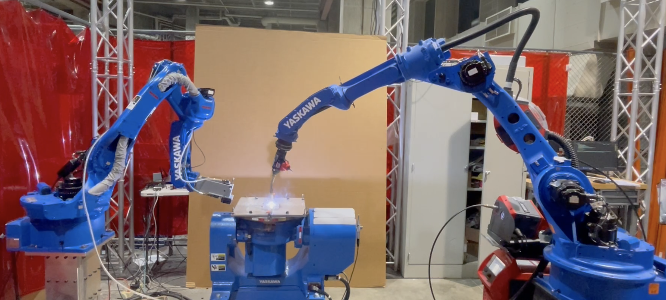
We consider a three-robot setup: a 6-DoF welding robot, a 2-DoF trunnion platform, and a 6-DoF sensing robot with a wrist-mounted laser line scanner measuring the printed part height profile.
Framework
After the deposition of each layer and scanning, the part geometry is reconstructed, with each scan registered to the positioner frame using the forward kinematics of the scanning robot and the positioner. Sampling the surface along the welding path gives the height profile of the top surface. For each layer, the slicing algorithm generates the desired layer height Δℎ𝑑 . The measured height profile of the current layer is compared with the desired profile and the difference, together with the torch speed to height model, generates the robot motion for the next layer.
Performance Comparison: Wall
Even through visual observation alone, it is evident that the quality of the printed piece has significantly better layer uniformity with the closed-loop approach. Note that defects tend to occur predominantly at the edges of the weld piece due to the arc on/off effects. In the open loop case, the height variation in each layer accumulates with the number of layers, while the proposed Scan-n-Print approach is able to correct the height variation in each layer.
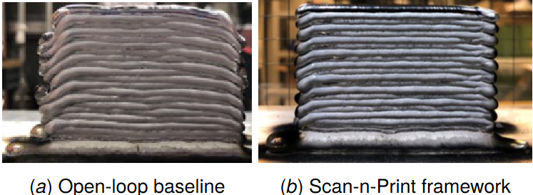
Open-loop baseline vs. Scan-n-Print for a wall structure, ER 4043 aluminum alloy.
Performance Comparison: Blade and Steel Material
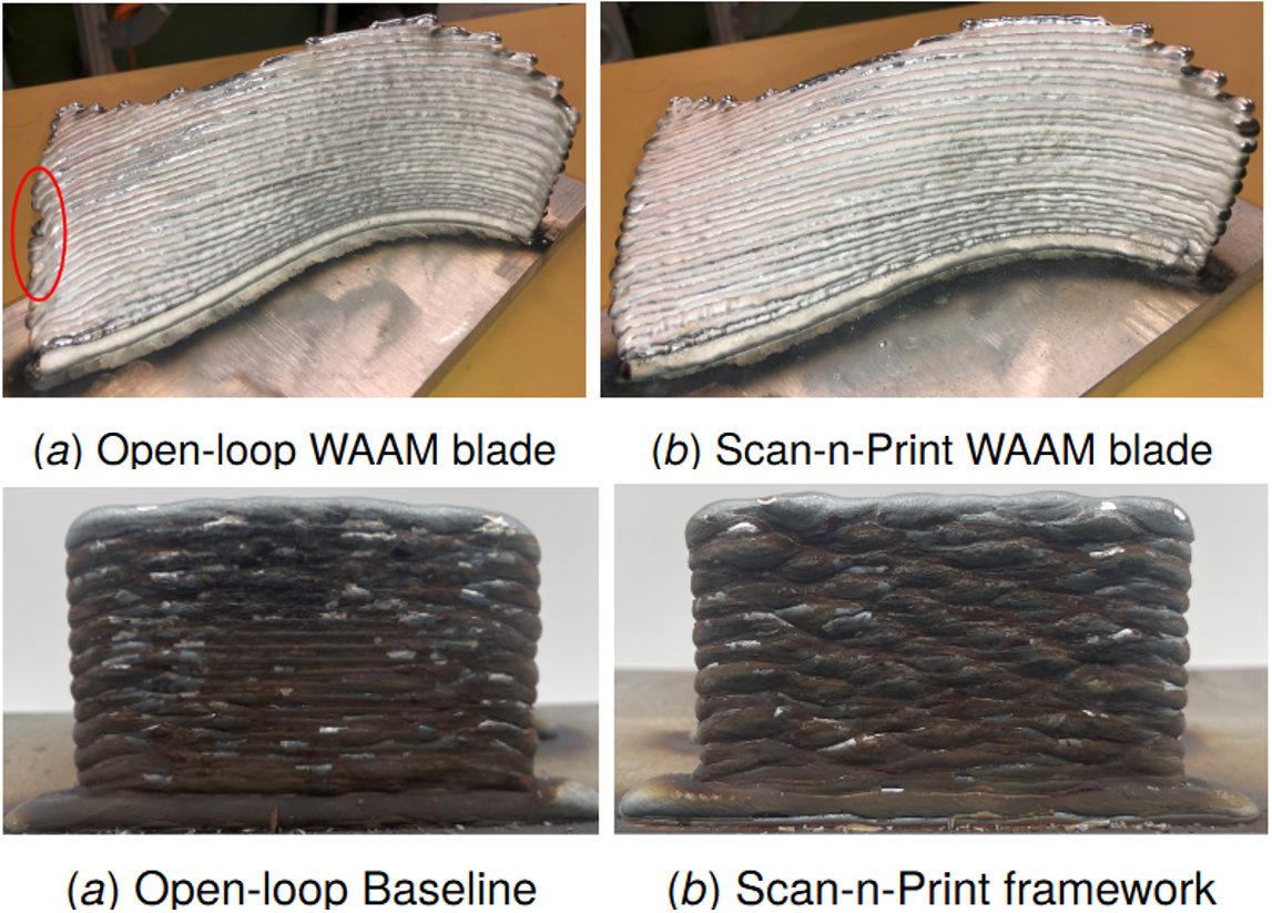
A visual comparison reveals a clear defect at the edge (indicated by the red circle) in the open loop case, where the welding torch fails to deposit sufficient material at the edge of the piece.
We applied the same approach to a steel alloy (ER 70S-6) and observed similar results. By visual observation, the open-loop welding with steel alloy does not create as much edge defects as with the aluminum alloy. This is because the steel alloy has higher melting point and lower thermal conductivity and is more stable than aluminum alloy. However, the top layer is still slightly curved compared to the close-loop approach.